 【关注川源科技HiCY】
-

 服务热线 400-700-2017
服务热线 400-700-2017
服务热线 400-700-2017
搜索更多信息
1. Research Background
Ion exchange membranes (IEMs) are core components of electrochemical water treatment, energy generation, and storage technologies, and the optimization of their performance is critical to improving overall process efficiency. However, there is currently a lack of recognized standardized methods for measuring the ionic conductivity of IEMs, which limits the accurate evaluation and optimization of their performance. To overcome this challenge, this study aims to develop a reliable experimental setup and method that can accurately measure the ohmic resistance of IEMs, thereby achieving accurate determination of ionic conductivity.
2. Abstract
The article introduces a recent study on the measurement of ionic conductivity of IEMs. The research team developed a new procedure for accurately measuring the ohmic resistance of IEMs through direct contact method and electrochemical impedance spectroscopy (EIS) technology. The study decoupled the membrane resistance from the external resistance by adopting experimental designs with different path lengths and electrode areas in two configurations, through the plane (TP) and in-plane (IP). At the same time, the impedance data was collected using EIS technology, and the consistency between the equivalent circuit model and the collected data was evaluated by analyzing the Nyquist plot and Bode plot. In addition, the study also discussed in detail the impact of experimental parameters such as electrode area, solution concentration and temperature on the measurement results, and put forward best practice recommendations.
3. Content Description
3.1 Experimental setup and methods
The experimental setup for this study consists of a hydrated IEM with two electrodes in contact. Due to imperfect contact, some solution (pure water or salt solution) is usually present between the membrane and the electrodes. The experiments were conducted using the direct contact method and the ohmic resistance of the membrane was measured by the EIS technique. EIS is a well-established technique for characterizing the electrical response of different materials and interfaces. In EIS experiments, impedance measurements are performed with a small oscillating current or potential signal over a wide frequency range (from MHz to mHz), which allows the decoupling of different rate phenomena.
The experimental process mainly includes two steps: one is to collect EIS spectra through TP configuration and IP configuration; the other is to decouple the membrane resistance and external resistance through path length modulation technology.
In the TP configuration, the membranes are stacked to tune the path length across the membrane. Two different approaches were used: one using measurements with individual membranes of different thicknesses and the other using stacks of membranes with similar thicknesses. By plotting the cell's area resistance versus membrane thickness, the interface resistance and membrane resistance can be decoupled.
In the IP configuration, a standard four-electrode probe is used to vary the path length at three unique distances, thereby isolating the film impedance response. This approach allows control of the path length between electrodes in the IP orientation and decouples the film resistance from the interface resistance by measuring the resistance between electrodes at multiple lengths along the sample.
3.2 Data Collection and Analysis
During the experiment, EIS spectra were collected under different conditions (e.g. different film thickness, different electrode area, different salt solution concentration, etc.) and reported on Nyquist and Bode plots (Figure 1). The Nyquist plot is obtained by plotting the negative imaginary impedance -Z” against the real impedance Z’, while the Bode plot is obtained by plotting the total impedance Z and the phase angle φ as a function of frequency.

Figure 1. a) Nyquist plot with imaginary impedance (-ZIm) versus real impedance (ZRe) b) Bode plot with impedance modulus (Z) and phase angle (φ) versus frequency (ω)
To extract information from the EIS results, the research team used a path length modulation technique rather than the traditional equivalent circuit fitting method. This method separates the true membrane resistance from any external resistance by regressing the total impedance response of the cell to a controlled input with a known effect on the membrane resistance (i.e., the path length through the membrane).
3.3 Results and Discussion
3.3 Results and Discussion
In the TP configuration, it was experimentally found that the residual impedance of the cable and sample holder has a significant effect on the EIS spectrum in the high-frequency region (Figure 2). This effect can be eliminated by performing open-circuit and short-circuit compensation, but it is usually unnecessary. The x-intercept of the uncompensated data usually provides a good estimate of the low-frequency intercept of the semicircular feature, which represents the total cell impedance. When the membrane resistance becomes larger, the compensation effect becomes less important, and the semicircular feature is obvious without any compensation.

Figure 2. Nyquist plot - EIS spectrum of a typical IEM tested in TP configuration
In addition, the experiment also found that the electrode area has a significant effect on the measurement of membrane ionic conductivity. When a small area electrode is used, the ionic conductivity of the membrane is abnormally high due to the inhomogeneous electric field that appears at the edge of the electrode. This edge effect can be reduced in relative importance by increasing the radius of the electrode. The experimental results show that the ionic conductivity decreases as the ratio of electrode circumference to area decreases (i.e., the electrode radius increases), and eventually approaches the value obtained from experiments where the stripe effect does not exist.
Results and analysis under IP configuration
In the IP configuration, the experiment successfully controlled the path length between electrodes in the IP orientation by measuring the resistance between electrodes at multiple lengths along the sample. Similar to the TP method, the slope of the area resistance versus path length yields the membrane ionic conductivity. Meanwhile, the intercept in the zero electrode spacing limit represents the interface resistance at the IP electrode. The experimental results show that this method can effectively decouple the membrane resistance from the interface resistance.
In addition, the research team also compared the effectiveness of three techniques for measuring the ohmic resistance of the membrane: TP changing the membrane thickness (as shown in Figure 3), TP stacking the membrane, and IP changing the length. The results showed that all three techniques can reliably measure the ohmic resistance of the membrane and decouple the membrane resistance from the interface resistance. However, the more commonly used and widely accepted EIS experimental methods (such as two-electrode TP measurement and four-electrode IP measurement of a single sample) cannot take into account the interface resistance in their direct implementation, and therefore may lead to large measurement errors.

Figure 3. Area resistance of membranes SPM-GDMA(46) and SPM-GDMA(59) equilibrated with 0.05 M NaCl solution as a function of membrane (or stack) thickness
4. Conclusion
This study developed a new method to accurately measure the ohmic resistance of IEMs by using the direct contact method and EIS technology. This method can clearly obtain the membrane resistance from the EIS results without designing a complex equivalent circuit. The experimental results show that the path length modulation technology under both TP configuration and IP configuration can effectively decouple the membrane resistance from the external resistance. At the same time, the study also found that the electrode area has a significant effect on the measurement of membrane ionic conductivity, and proposed corresponding solutions.
Compared with other methods and analyses used in the literature, the results of this study have some inconsistencies. These inconsistencies may be due to factors such as differences in experimental conditions, sample preparation methods, and data analysis methods. Therefore, when performing ionic conductivity measurements, it is necessary to pay attention to the impact of these factors on the results and take appropriate measures to reduce errors.
In summary, this study provides a new and reliable method for measuring the ionic conductivity of IEMs. This method has the advantages of simple operation, high accuracy, and wide application range, and is expected to provide strong support for the performance optimization and application expansion of IEMs. Future research can further explore the ion transport mechanism of IEMs under different conditions and how to improve the accuracy and reliability of measurements.
Literature Source
Díaz J C, Kitto D, Kamcev J. Accurately measuring the ionic conductivity of membranes via the direct contact method[J]. Journal of Membrane Science, 2023, 669: 121304.
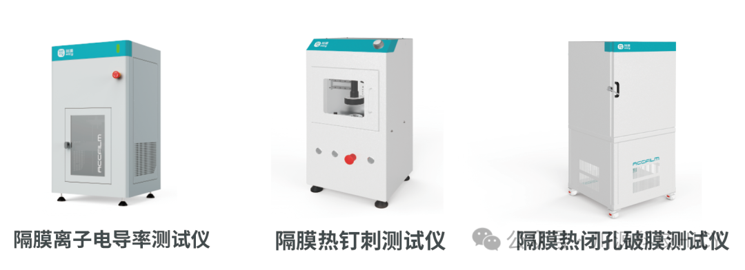
Hicy's fuel cell ion exchange membrane conductivity tester is a device based on the AC impedance method, adopts a high-precision parallel guarantee structure design, and is equipped with a fully closed-loop intelligent servo control system, impedance analysis system, and temperature and humidity sensors to realize the detection of membrane ion conductivity characteristics.

Follow us to learn about the latest trends in the battery testing industry
For business consultation, please call our service hotline
400-700-2017